Monday 17 December 2012

Topic 5 Subtopic 4 Making a Reference To A Memory

Making a Reference To A Memory

For making a reference to a memory using 32-bit register and an offset a 32-bit, lw or sw cannot use to achive this. The main reason of this is MIPS instruction formats cannot support 32 bit constants. Therefore an arbitrary 32-bit immediate constant cannot load into a register in a single instruction without performing a data load from memory. By using 16-bit Thumb instructions, the range of constants generated is much smaller and so the task could not be perform.

Immediate implies the constant is part of the instruction. 
This is the part where lui (load upper immediate) function. The instruction looks like:
  
lui  $rt, immed
 
This is an I-type instruction. $rs is ignored. It can have any value.


InstructionB31-26B25-21B20-16                B15-0                
opcoderegister sregister timmediate
lui $rt, immed001 111ignored-immed


The dashes are 5-bit encoding of the register number in UB. Example, $r7 is encoded as 00111. The offset is represented in 16-bit 2C.
For lui function, it direct copies its 16-bit immediate operand to the upper two bytes of the designated register. Therefore the lower 16 bit is all 0's.

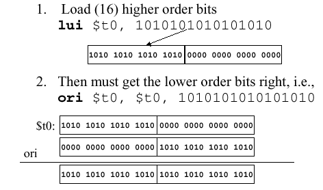
Suppose we want to load a 32-bit word into register, as already say MIPS only supports 16-bit constants. Therefore there is a trick to achieve it. First is to load the higher-order bits using the lui instruction

lui $t0, 10101010101010101010

which it will loads the constant (2nd operand) into the upper two bytes (significant 16 bits) of $t0. For the remainder of the lower order bits, it can be load using the ori (or-immediate) instruction.

ori $t0, $t0, 10101010101010101010
In diagram:


Another way is using addi.
lui $r1, 0x0123
addi $r1, $r1, 0xabcd

This is not recommended to use because it has problem, which is when the immediate value is negative, it will make the upper 16 bits all be 1's, and that time using addi will ruin the upper 16 bits.
Therefore it is better to use ori more than addi.

Using $at
The pseudo instruction, li $rt, immed loads an immediate value to a register, and this can be a 32 bit value. The instruction is translated to:

lui  $at, 0x0123
ori  $at, $at, 0xabcd

$at is actually register $r1. This register is used for translating pseudoinstructions to real instructions. If wants to avoid clobbering other registers during translation, $at is reserved specifically for this purpose.The assembler must represent immediate value as a 32 bit 2C binary number if the immediate value is written in base 10, then need to split the high 16 bits for the lui instruction and the low 16 bits for the ori instruction.


By SOON BOON JIAN
B031210199


Sunday 16 December 2012

topic 5 - sub 3 :- Data transfer: Register to memory

Registers and Memory

Registers are storage locations internal the the processor. CPU instructions operate on these values directly. On RISC processors, all data must be moved into a register before it can be operated. On CISC (Intel) chips, there are a few operations that can load data from RAM, process it, and save the result back out, but the fastest operations work directly with registers.

Each register also has a size that determines the maximum amount of data that can be processed at a time. The registers on Pentium chips, for example, are 32 bits.

Finally, there are generally only a few registers available on a processer. Intel chips, for example, have 6 general purpose registers, and several specialized registers including a base register, stack register, flags register, program counter, and some addressing registers.

Memory, or RAM, is located external to the CPU. Generally speaking, data has to be loaded into a CPU register from memory before the CPU can process it, RAM is much slower than registers, there is a lot more RAM than registers, and generally memory can be addressed on a byte boundaries, where registers may not be able to access all the bytes in a register.


The 32 MIPS registers are partitioned as follows:

Register 0 : $zero always stores the constant 0
Regs 2-3 : $v0, $v1 return values of a procedure
Regs 4-7 : $a0-$a3 input arguments to a procedure
Regs 8-15 : $t0-$t7 temporaries
Regs 16-23: $s0-$s7 variables
Regs 24-25: $t8-$t9 more temporaries
Reg 28 : $gp global pointer
Reg 29 : $sp stack pointer
Reg 30 : $fp frame pointer
Reg 31 : $ra return address


Memory-register operation

The data transfer instruction that copies data from memory to a register is traditionally called load.
The format of the load instruction is the name of the operation followed by the register to be loaded, then a constant and register used to access memory.The sum of the constant portion of the instruction and the contents of the second register forms the memory address.The actual MIPS name forthis instruction is lw, standing for load word.


Data may be copied to and from memory and registers by a MOV instruction which may transfer 8-bits, 16-bits, or 32-bits of data. Instead of using words like load, store or copy, using MOV or  words move of the operation to make a copy of the state of the object at A and overwrites the old state of B in this process. The operands for the MOV commands can either be registers, a segment register or a memory address since the command is executed in a single CPU work cycle.

For example.There is a succession as in:
-  move the contents of the memory into the register ax:

MOV ax, [address1]
 
- also move the contents of the register bx into the register ax

MOV ax, bx
 
- move the contents of the register ax into the referenced memory block 

MOV [address], ax


However, Memory to memory moves, such as
 
MOV [address1], [address2]
 
are not possible. To achieve this, MOV must be used in sequence:
 
MOV ax, [address2]
MOV [address1], ax 


GOH MENNING
B031210149

Topic 4 Subtopic 4 Data Representation

Data Representation

In MIPS, we must understand how a computer represent a data from the viewside of MIPS programming language. This is important because it help us to understand how to perform computations and also manipulate data in MIPS program.

All data on digital computers is represented as a sequence of 0s and 1s. This includes numeric data, text, executable files, images, audio, and video. The ASCII standard associates a seven bit binary number with each of 128 distinct characters.

Character Representation


ASCII codes table - Format of standard characters


1 byte has 8 bits, and a character can be represented with one byte. Most of the computer offer 8-bit byte to represent characters following the ASCII(American Standard code for Information Interchange) as the standard for character representation. Above is the table of ASCII.

The ASCII bit patterns is assembled and to be placed in memory. For example:
.asciiz "X Y"  The bit pattern that will produced in object module is
     58 20 59 00
For number represent hexadecimal system, the front of each number can be written as 0x. For example for character "X", it corresponds to bit pattern 0x58, while 0x00 is NUL, which used by the assembler to show the end of string character. For "X Y", it can be write also as
.byte    88 32 89 00

Number Representation
In MIPS, number did not represented in binary system but in decimal or hexadecimal system. In order to insert number to a register, first we need to know the kind of number system which we want to write in the program.
Example, if want to load 16 into register $4, we have two ways to represent the decimal 16.
1. ori $4, $0, 16  (in decimal system)
2. ori $4, $0, 0x10  (in hexadecimal system)
We need to choose the number system using when want to load number into register.


SOON BOON JIAN
B031210199

Topic 3 subtopic 4: PC relative addressing


PC-relative addressing


In order to load a register from a "constant" stored in program memory which is short distance away from the current instruction, PC-relative addressing mode is used. It can be seen as a special case of the "base plus offset" addressing mode, which selects the program counter (PC) as the "base register". 

It usually used in conditional branches. PC in PC-relative addressing mode bring a meaning of "special purpose register, Program Counter", which address of next instruction to be fetched are stores inside. 
The offset is the number of instructions forward or backward that must be skipped to get to the instruction labeled Label. The offset value can be an interpreted label value or immediate value. 

Thus, 4*offset + PC+4 is the address of the instruction labeled with Label.
The effective address is the sum of the Program Counter and offset value in the instruction. The branch target is determine by effective address.

PC-relative addressing occurs in branch instructions, such as beq and bne. These instructions are I-type instructions, with the following format.


The immediate value is only 16 bits, which means we can't address a large range of memory.
 To implement loops or if-else statements, Branch instructions are used primarily.
When jump to a statement in an if-else or loop, we will  typically jump to a nearby instruction from the one we jumped from. It makes sense to jump relative to the PC, because the instruction we jumped from must have been the one at PC
For example, if you had a branch instruction at address 1000, then normally you'll jump somewhere near the branch instruction.


PC relative addressing in action


Below diagram shows how an effective address is generated when using PC relative addressing mode.


SOON BOON JIAN
B031210199

topic 4 - sub 3 : system calls and MIPS Assembly Languages Program Format

System Calls

MIPS programs can make system calls (syscall) by placing parameters in specified registers, depending on the call, and executing a trap instruction. Returned results are made available in other specified registers, also depending on the call. System call allows user(s) to call upon the basic system functions. To use syscall, first set $v0 with the code of the function you want to call, then only use syscall. The exact codes available may depend on the specific system used, but the following are examples of common system calls.


                                                        Table : System call functions


* In SPIM, exception handler is used like :

li   $v0, code     # Load $v0 with the "system call code"
                         # number of an OS service
.........                # Put parameters for the service in
.........                # registers $a0, $a1
syscall               # Invoke the operating system
                         # Return value (if any) is in $v0 or $f0


* Examples of simple I/O for lab today :

# print an integer (Exp. number 7)
li   $a0, 7 --> loads the number we want to print into the first argument register
li   $v0, 1 --> stores the code for the print integer call into $v0
syscall      --> Executes system call

# print a null-terminated string
li   $v0, 4 --> loads service number in $v0
la $a0, prompt_string --> loads address of string to be printed into $a0
syscall

.data  --> the null-terminated string must be defined in data segment
prompt_string: .asciiz "Enter a value: "

# read in an integer
li   $v0, 5 --> loads service number in $v0
syscall --> the value entered by the user is returned in $v0
move $t0, $v0 --> store value entered into another register

# terminates execution of program
li   $v0, 10 --> loads service number in $v0
syscall


MIPS Assembly Languages Program Format

MIPS assembler program is a plain text file that made up of two types of statements:

  • Assembler directive that tells the assembler how to translate a program but cannot be translated into machine code.
  • Executable instruction, where upon execution will be translated into machine code. Sometimes can be referred as program code.


# Label (Optional)


The label portion of a statement must begin in column 1 and must end with a " : ". The " : " is not part of the label. It only serves to visually distinguish a new label definition from other program elements.

Each label represents a memory address in assembly language. It could be the address of data or the adddress of an instruction (i.e. labels can appear in both .text and .data sections).

A label represents the address of the instruction or data element that immediately follows it, whether it follows on the same line or a subsequent line.

Labels defined in a .data section are like variable names in HLLs, and follow the same naming rules. They must begin with a letter or underscore, and can contains letters, underscores, and digits.

A label is used to mark a specific point in the program code. In this case, when instruction of BRANCH or JUMP call for a specific label, the program will execute from the point of the label is situated.
Example:

* main :  sll     $0,$0,0
              sll     $0,$0,0
              sll     $0,$0,0
              sll     $0,$0,0
              j       main         # jump to the point labeled main
              addiu $8,$8,1


# Opcode (Operational Code)

Opcode is the portion of a machine language instruction that specifies the operation to be performed. Their specification and format are laid out in the instruction set architecture of the processor.

Opcode is the field that denoted the basic operation and format of an instruction. Mnemonic language is used rather than hexadecimal code for the purpose of simplicity and readability.

These tables list the available operations in MIPS. For each instruction, the 6-bit opcode or function is shown.


# Operand

Operand may contain registers, shift amount, label to jump into and constant or address.

  • Specify the data required by the operation
  • Operands can be registers, memory variables, or constants
  • Most instructions have three operands
Example:
               addiu   $t0,$t0,1    # increment $t0


Comment

In MIPS assembly, comments are denoted with a number sign "#". Everything after that sign on the same line is a comment and is skipped by the assembler's lexer.

MIPS program structure is just a plain text file with data declarations and program code. The name of file should end in suffix .asm to be used with SPIM simulator. Data declaration section should be followed by program code section.

  • Data declarations are placed in section of program identified with assembler directive .data.
    - Variable names used in the program are declared with storage allocation set in main memory
       (RAM).
    - Revise data representation sub-chapter to identify which data type to use on the declaration.
  • Code is placed in section of program identified with assembler directive .text.
    - The section contains program code (instructions to be executed).
    - Starting point for code excution is from a certain label at the left column where the programmers
       usually use main:
    - Ending point of main code should use exit system call.
Example : 

label        Section/code           Comments     
                  
               .data                       # variable declaration
               .text                        # Code section
main:                                      # indicates start of code
                ori   $8,$0,0x2       # next instruction


GOH MENNING
B031210149

Topic 3 - subtopic 5 : Pseudo-direct addressing

Pseudo direct addressing

In direct addressing, an address is specified in the instruction. The J-type instruction ideally would use direct addressing to specify a 32-bit jump target address (JTA) to indicate the instruction address to execute next. However, the J-type instruction encoding does not have enough bits to specify a full 32-bit JTA.

J-type Instructions
  • jr uses register addressing: it’s an R-type instruction
            –jr $31 ($ra)


  • j and jal use pseudo-direct addressing: J-type
                  – Looks like immediate addressing in assembler
                   – allows 26 bits instead of 16
  • For example: j 10000 and jal 10000:


Addressing for jump


Pseudo-Direct addressing is specifically used for J-type instructions, j and jal. The instruction format is 6 bits of opcode and 26 bits for the immediate value or target.


The effective address is calculated by taking the upper 4 bits of the Program Counter (PC), concatenated to the 26 bit immediate value, and the lower 2 bit are 00.

The  new effective address, any operand to an instruction which references memory
is always be word aligned (means an address must be multiple of 4) and only have ( 0 0 ) 2-bit target address of jump instruction to create a complete 32-bit address. Take the top 4 bits of the PC, concatenate that with the 26 bits that make up the target, and concatenate that with 00. The jump target is constrained to anywhere within 256MB block of code (1/16 of the total 4GB address space) with the R-type instruction jr and jalr are used, where complete 32-bit target address is specified in a register since the upper 4 bits of the PC is used. The new 32-bit address of the PC is produced.

For example: J label


implementation of Pseudo-direct Addressing


LIEW JUN JIE
B031210374